Inverted Metallurgical Microscopes
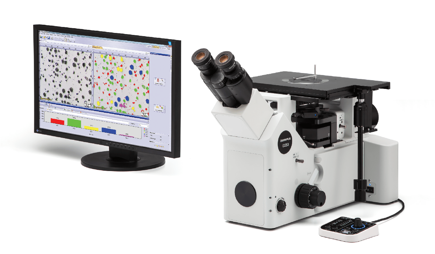
Quickly observe, measure, and analyze metallurgical structures.
Advanced Analysis Tools
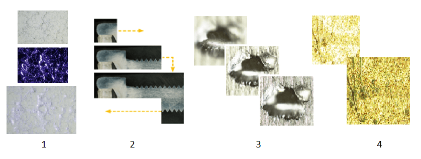
1. Combined observation methods produce exceptional images
2. Easily create panoramic images
3. Create all-in-focus images
4. Capture both bright and dark areas
1. Software designed for materials science
2. Metallurgical analysis that complies with industrial standards
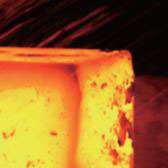
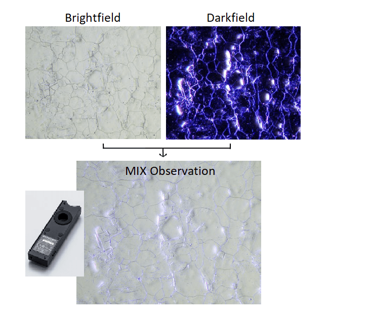
MIX technology produces unique observation images by combining darkfield with another observation method, such as brightfield or polarization. MIX observation enables users to view samples that are difficult to see with conventional microscopes, and represents even small height differences of sample surfaces. The circular LED illuminator used for darkfield observation has a directional darkfield function where one or more quadrants are illuminated at a given time. This reduces a sample’s halation and is useful for visualizing its surface texture.
Sample: Stainless Steel
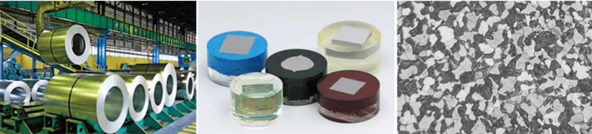
Optimized for Materials Science
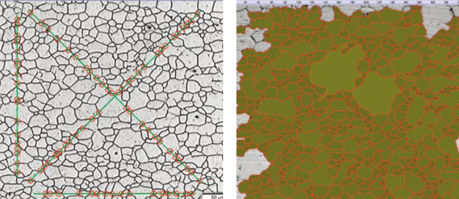
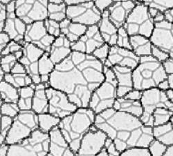
Grain Sizing in a Microstructure
Measure the grain size and analyze the microstructure of aluminum, steel crystal structures, such as ferrite and austenite, and other metals.
Supported standards: ISO, GOST, ASTM, DIN, JIS, GB/T
Sample: Microstructure of ferritic grains (Intercept and Planimetric)
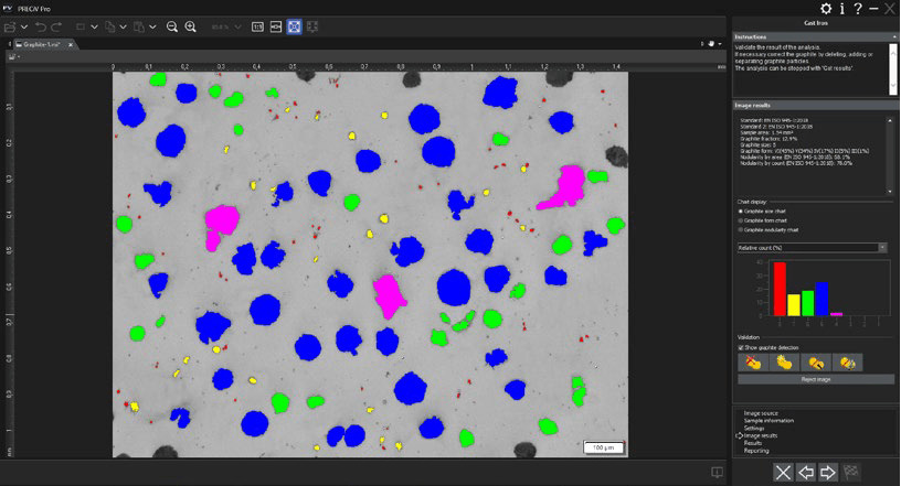
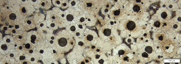
Evaluating Graphite Nodularity
Evaluate the graphite nodularity and content in cast iron samples (nodular and vermicular). Classify the form, distribution, and size of graphite nodes.
Supported standards: ISO, NF, ASTM, KS, JIS, GB/T
Sample: Ductile cast iron showing nodular graphite
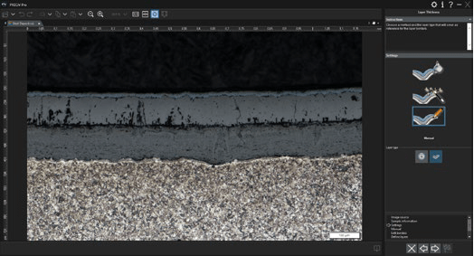
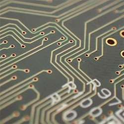
Measure the layer/coating thickness
Many industries, such as automotive, aerospace, and oil and gas, use a multi- or monolayer coating as a protective layer against corrosion, fire, heat, stress, and ultraviolet (UV) light. Producing a homogenous coating of a certain thickness is critical for product quality
Supported standards: EN 1071: 2002, VDI 3824: 2001
Material Solution Specification
| Solutions | Supported standards |
| Grain intercept | ISO 643: 2012, JIS G 0551: 2013, JIS G 0552: 1998, ASTM E112: 2013, DIN 50601: 1985, GOST 5639: 1982, GB/T 6394: 2002 |
| Grain planimetric | ISO 643: 2012, JIS G 0551: 2013, JIS G 0552: 1998, ASTM E112: 2013, DIN 50601: 1985, GOST 5639: 1982, GB/T 6394: 2002 |
| Cast iron | ISO 945-1: 2010, ISO 16112: 2017, JIS G 5502: 2001, JIS G 5505: 2013, ASTM A247: 16a, ASTM E2567: 16a, NF A04-197: 2004, GB/T 9441: 2009, KS D 4302: 2006 |
| Inclusion worst field | ISO 4967 (method A): 2013, JIS G 0555 (method A): 2003, ASTM E45 (method A): 2013, EN 10247 (methods P and M): 2007, DIN 50602 (method M): 1985, GB/T 10561 (method A): 2005, UNI 3244 (method M): 1980 |
| Chart comparison | ISO 643: 1983, ISO 643: 2012, ISO 945: 2008, ASTM E 112: 2004, EN 10247: 2007, DIN 50602: 1985, ISO 4505: 1978, SEP 1572: 1971, SEP 1520: 1998 |
| Coating thickness | EN 1071: 2002, VDI 3824: 2001 |
| Optical systemOptical system | UIS2 optical system (infinity-corrected) | |
|---|---|---|
| Microscope frame | Reflected light illumination | Manual brightfield/darkfield selection by mirror unit Manual field stop/aperture stop switch with centering Light source: White LED (with Light Intensity Manager) /12 V, 100 W halogen lamp/100 W mercury lamp/light guide source Observation mode: brightfield, darkfield, differential interface contrast (DIC)*1, simple polarizing*1, MIX observation (4 directional darkfield)*2 *1 Slider for exclusive use of this observation is required. *2 MIX observation configuration is required. |
| Imprinting of scale | All ports reversed positions (up/down) from observation positions seen through the eyepiece | |
| Output front port (optional) | Camera and DP system (reversed image, special camera adapter for GX) | |
| Output side port (optional) | Camera, DP system (upright image) | |
| Electrical system | Reflected light illumination Built-in LED power supply for reflected light illumination Continuously-variable light intensity dial Input rating 5 V DC, 2.5 A (AC adapter 100–240 V, AC 0.4 A, 50 Hz/60 Hz) External interface (requires the optional BX3M-CBFM control box) Coded nosepiece connector × 1 MIX Slider (U-MIXR-2) connector × 1 Handset (BX3M-HS) connector × 1 Handset (U-HSEXP) connector × 1 RS-232C connector × 1, USB 2.0 connector × 1 |
|
| Focus | Rack and pinion with roller guide Manual, coarse and fine coaxial handle; focus stroke 9 mm (2 mm above and 7 mm below the stage surface) Fine handle stroke per rotation: 100 μm (min. scale: 1 μm) Coarse handle stroke per rotation: 7 mm With torque adjustment ring for coarse focusing With upper limit stopper for coarse focusing |
|
| Tubes | Widefield (FN 22) | Inverted: binocular (U-BI90, U-BI90CT), tilting binocular (U-TBI90) |
| Nosepiece | Brightfield Holes: 4 to 7 pcs, Type: Manual/Coded, Centering: Enabled/Disabled Brighfield/darkfield Hole: 5 to 6 pcs, Type: Manual/Coded, Centering: Enabled/Disabled |
|
| Stage | Right handle stage for GX (X/Y stroke: 50 × 50 mm, max. load 5 kg) Flexible right handle stage, left short handle stage (each X/Y stroke: 50 × 50 mm, max. load 1 kg) Gliding stage (max. load 1 kg) A set of teardrop and long hole types |
|
| Weight | Approx. 25 kg (microscope frame 20 kg) | |
| Environment | ・Indoor use ・Ambient temperature: 5 to 40 °C (45 to 100 °F) ・Maximum relative humidity: 80% for temperatures up to 31 °C (88 °F) (without condensation) In case of over 31 °C (88 °F), the relative humidity is decreased linearly through 70% at 34 °C (93 °F), 60% at 37 °C (99 °F), and to 50% at 40 °C (104 °F). ・Pollution degree: 2 (in accordance with IEC60664-1) ・Installation/Overvoltage category: II (in accordance with IEC60664-1) ・Supply voltage fluctuation: ±10 % |
|