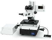
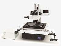
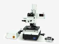
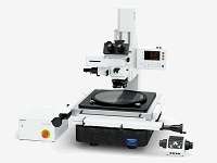
X,Y,Z axis Coordinate Measurement Microscope
The STM7 series uses the same UIS2 infinity-corrected optical system found in state-of-the-art optical microscopes.
As a result, observed images have high resolution and high contrast, with aberration thoroughly eliminated to help ensure highly accurate measurement in minute detail.


To further improve measurement accuracy, the STM7 series uses a highly durable, vibration-resistant frame with a granite surface plate. This stability enables sub-micron level measurements with minimal error.
As modern manufacturing technology becomes increasingly miniaturized and precise, highly accurate measurements are even more essential—not only along the XY axis, but also along the Z-axis. Olympus responded by creating the first reflective active, confocal autofocus system.


The accuracy of Olympus’ measuring microscopes is controlled by a strict traceability system, and Olympus even offers traceable calibration at the time of installation.
- Calibration certificate issued by Olympus Corporation Test & Analysis Center, and authenticated by ILAC-MRA calibration accreditation agencies (JCSS, JAB).
- Traceability systems vary depending on periods and countries/regions. The samples used in STM7 calibrations are calibrated in each country/region. Please ask Olympus for details.
Five configurations provide you with flexibility to choose the features that you need.
Stage: 100 mm x 100 mm
Stage: 200 mm x 200 mm


Stage: 100 mm x 100 mm
Stage: 200 mm x 200 mm
Stage: 300 mm x 300 mm
Stage: 100 mm x 100 mm
Stage: 200 mm x 200 mm
Stage: 100 mm x 100 mm
Stage: 200 mm x 200 mm
Stage: 300 mm x 300 mm
BF: Brightfield
DF: Darkfield
DIC: Differential interference contrast
POL: Polarized light
: Option
| STM7 - SF | STM7 - MF | STM7 - LF | STM7 - MFA | STM7 - LFA | |
| Z-axis focus | Manual | Manual | Motorized | ||
| Standard | BF or BF/DF | BF or BF/DF | BF or BF/DF | ||
| Option | DIC/POL | DIC/POL | DIC/POL | ||
|
Measurement objectives |
|||||
|
Focus navigator |
|||||
|
Autofocus unit |
|||||
|
Measurement support software |
|||||
|
Measurement support software |
|||||
- Short measurement stroke precludes the measurement of larger samples•Samples must be rotated because the X-axis measurement area is shorter than the Y-axis measurement area
- Due to the narrow measurement range, it is impossible to line up large numbers of samples on the stage to measure them at the same time
- The STM7 features a 300 mm x 300 mm stage capable of measuring large samples, including 300 mm wafers and printed circuit boards.
- The X- and Y-axis measurement areas are equally long, eliminating the need to rotate samples
- Long measurement areas for both the X and Y-axis allow multiple samples to be lined up on the stage for more efficient measurement
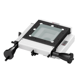
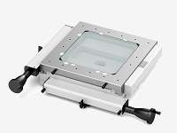
Three stages are available, each with a different measurement stroke - 100 mm x 100 mm, 200 mm x 200 mm, and 300 mm x 300 mm. Whether your samples are large or small, we offer a stage that fits your application.

100 mm x 100 mm

200 mm x 200 mm

300 mm x 300 mm
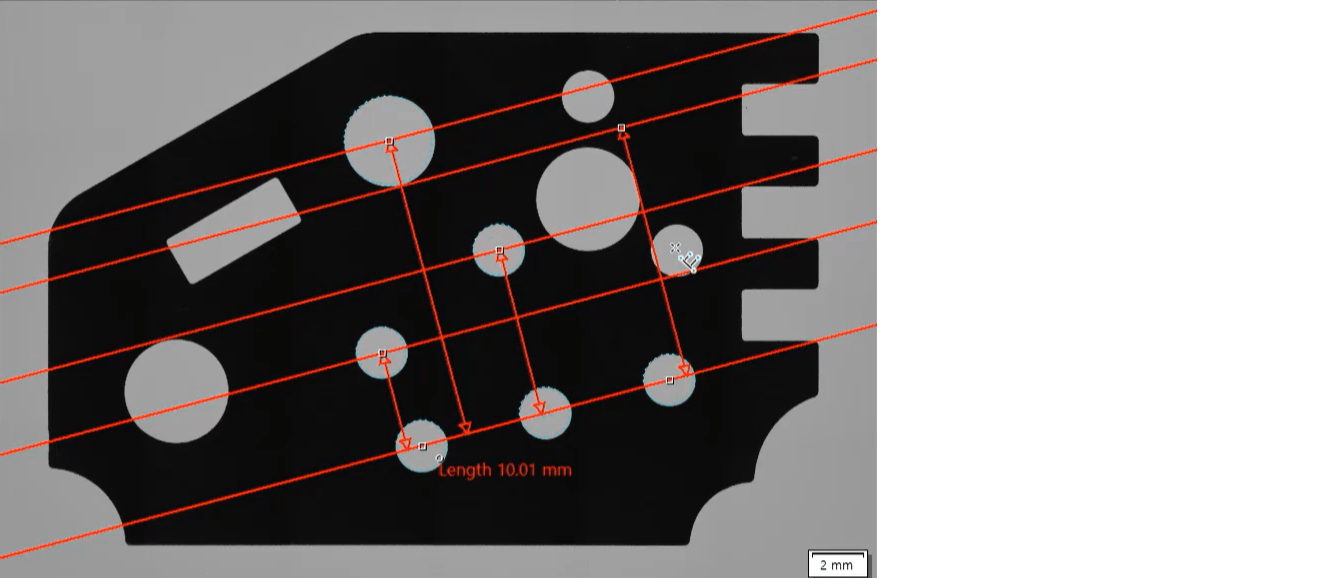
- When doing visual measurement, variations can arise in the height measurements between different operators. Furthermore, this measurement method is time-consuming and inefficient
- The STM7 focus navigation system reduces the operator subjectivity in height measurements. It also shortens the time required to perform height measurement to achieve greater efficiency
Olympus’ focus navigator delivers highly reproducible height measurement by projecting a pattern within the field of view and identifying vertical deviations. Slight errors can occur in height measurements taken with normal visual observation, even when focus appears to be sharp. The focus navigator, however, enables measurements to be made simply by matching up the marks, reducing operator subjectivity in measurement results.

The ability to clearly and easily see the output display component of measuring microscopes is essential. Olympus measurement software deliver complex measurements with greater accuracy. The software also enables the use of digital cameras.

The 300 mm square length stage enables the same measurement stroke to apply to both the X and Y-axes, which means it can be used to measure large samples, such as 300 mm wafers and printed circuit boards without changing their orientation.

SPECIFICATIONS OF STM7 (Manual Model) |
|
|
Manual Model | ||||
|
|
Small stage | Midsize stage | Large stage | ||
| Microscope body |
|
STM7-SF | STM7-MF | STM7-LF | |
| Focus | Vertical movement range | 175 mm | 145 mm | ||
| Maximum measurable height | 120 mm (with measurement objective) 175 mm (with metallurgical objective) |
90 mm (with measurement objective) 145 mm (with metallurgical objective) *1 |
|||
| Z-axis measurement resolution | 0.1 um | ||||
| Z-axis drive method | Manual coaxial fine/coarse focusing knobs | ||||
| Illumination | LED illumination | White: for reflected light illumination, green: for transmitted light illumination | |||
| Observation tube | MM6-ETR Erect image trinocular tube (100:0/0:100) | ||||
| Eyepiece (F.N.22) | MM6-OCC10X (with cross hairs) , MM6-OC10X | ||||
| Objectives | BF (Bright field) | MM6C-KMAS Illumination |
|||
| U-5RES-ESD Nosepiece |
|||||
| MPLFL5X,10X,LMPLFLN20X,50X,100X Metallurgical objectives |
|||||
| BF (Brightfiels) /DF (Darkfield) | MM6C-RLAS Illumination |
||||
| U-D5BDRES-ESD Nosepiece |
|||||
| LMPLFLN5XBD,10XBD,20XBD,50XBD,100XBD Metallurgical objectives |
|||||
| LED unit | White color (Reflected) | MM6-ILW | |||
| Green color (Transmitted) | MM6-ILG | ||||
| Stage |
|
STM7-CS100 | STM7-CS200 | STM7-CS300 | |
| Measuring range | X-axis 100 mm, Y-axis 100 mm | X-axis 200 mm, Y-axis 200 mm | X-axis 300 mm, Y-axis 300 mm | ||
| Measurement accuracy (L: measuring length) |
(3+2L/100) μm | (3+4L/200) μm | (3+6L/300) μm | ||
| Accuracy assurance weight | 6 kg | 10 kg | 15 kg | ||
| Counter |
|
STM7-DI | |||
| Number of axes | Three | ||||
| Unit | μm / mm / inch / mil | ||||
| Minimum resolution | 0.1 um | ||||
| Control box | STM7-CB | ||||
| Hand switch | STM7-HS | ||||
| Focus controller | - | ||||
| Interface cable | - | ||||
| Anti-vibration plates | - | STM7-VI | |||
| Power cable | UYCP | ||||
| Dimensions (W x D x H) mm | 466 x 583 x 651 | 606 x 762 x 651 | 804 x 1024 x 686 | ||
| Weight (kg) | 84 kg | 152 kg | 277 kg | ||
| Power consumption | 100-120/220-240V - 50/60Hz 0.3A/0.2A |
100-120/220-240V - 50/60Hz 0.3A/0.2A |
100-120/220-240V - 50/60Hz 0.3A/0.2A |
||
*1 When using the large frame STM7-LF/STM7-LFA, a specimen whose height is 100 mm or less can be placed at the position backward from the light axis by 180 mm or more.
OBJECTIVES WORKING DISTANCE
| Objective | 1X | 3X | 5X | 10X | 20X | 50X | 100X | ||
| Measuring objectives | MM6-OB series | 59.6 | 76.8 | 65.4 | 50.5 | - | - | - | |
| Metallurgical objectives | MPLFLN series | Brightfield | - | - | 20.0 | 11.0 | 3.1 | 1.0 | 1.0 |
| LMPLFLN series | Long working distance | - | - | 22.5 | 21.0 | 12.0 | 10.6 | 3.4 | |
| MPLFLN-BD series | Brightfield/darkfield | - | - | 12.0 | 6.5 | 3.0 | 1.0 | 1.0 | |
| LMPLFLN-BD series | Brightfield/darkfield, long working distance | - | - | 15.0 | 10.0 | 12.0 | 10.6 |
3.3 |
|
SPECIFICATIONS OF STM7 (Motorized Model) |
|
|
Motorized Model | |||
|
|
Midsize stage | Large stage | ||
| Microscope body |
|
STM7-MFA | STM7-LFA | |
| Focus | Vertical movement range | 175 mm | 145 mm | |
| Maximum measurable height | 120 mm (with measurement objective) 175 mm (with metallurgical objective) |
90 mm (with measurement objective) 145 mm (with metallurgical objective) *1 |
||
| Z-axis measurement resolution | 0.1 um | |||
| Z-axis drive method |
Motorized
|
|||
| Illumination | LED illumination | White: for reflected light illumination, green: for transmitted light illumination | ||
| Observation tube | MM6-ETR Erect image trinocular tube (100:0/0:100) | |||
| Eyepiece (F.N.22) | MM6-OCC10X (with cross hairs) , MM6-OC10X | |||
| Objectives | BF (Bright field) | MM6C-KMAS Illumination |
||
| U-5RES-ESD Nosepiece |
||||
| MPLFL5X,10X,LMPLFLN20X,50X,100X Metallurgical objectives |
||||
| BF (Brightfield) /DF (Darkfield) | MM6C-RLAS Illumination |
|||
| U-D5BDRES-ESD Nosepiece |
||||
| LMPLFLN5XBD,10XBD,20XBD,50XBD,100XBD Metallurgical objectives |
||||
| LED unit | White color (reflected) | MM6-ILW | ||
| Green color (Transmitted) | MM6-ILG | |||
| Stage |
|
STM7-CS200 | STM7-CS300 | |
| Measuring range | X-axis 200 mm, Y-axis 200 mm | X-axis 300 mm, Y-axis 300 mm | ||
| Measurement accuracy (L: measuring length) |
(3+4L/200) μm | (3+6L/300) μm | ||
| Accuracy assurance weight | 10 kg | 15 kg | ||
| Counter |
|
STM7-DI | ||
| Number of axes | Three | |||
| Unit | μm / mm / inch / mil | |||
| Minimum resolution | 0.1 um | |||
| Control box | STM7-CBA | |||
| Hand switch | - | |||
| Focus controller | STM7-MCZ | |||
| Interface cable | U-IFCBL200 | U-IFCBL200 | ||
| Anti-vibration plates | STM7-VI | |||
| Power cable | UYCP | |||
| Dimensions (W x D x H) mm | 606 x 762 x 811 | 804 x 1024 x 844 | ||
| Weight (kg) | 159 kg | 284 kg | ||
| Power consumption | 00-120/220-240V 50/60Hz 0.6A/0.35A | 100-120/220-240V 50/60Hz 0.6A/0.35A | ||
*1 When using the large frame STM7-LF/STM7-LFA, a specimen whose height is 100 mm or less can be placed at the position backward from the light axis by 180 mm or more.
OPTION
| Objectives | Measurement objectives | MM6-OB series (1X /3X /5X /10X) |
| Focus navigator | Focus navigator unit | STM7-FN |
| Green LED unit | MM6-ILG | |
| Autofocus | Autofocus unit | STM7-AF |
| DIC | U-DICR DIC slider for reflected light | U-DICR |
| Software/Camera*1 | Measurement Support Software | STM7-BSW |
| Camera | Digital camera Low | STM7-CU |
| Digital camera Middle | DP23-CU | |
| Digital camera High | DP28-CU | |
| TV adapter | C-mount camera port tube with 0.5X lens | U-TV0.5XC-3 |
| C-mount camera port tube with 0.35X lens | U-TV0.35XC-2 | |
| Rotatable stage | For 100 x 100 mm | STM7-RS100 |
| For 200 x 200 mm | STM7-RS200 | |
| For 300 x 300 mm | STM7-RS300 | |
| ND filter | ND filter (Transmittance 6%) | U-25ND6 |
| ND filter (Transmittance 25%) | U-25ND25 | |
| DIC | DIC/Polarizer | U-PO3 |
| DIC/Analyzer | U-AN360-3 | |
| Software | MIA, EFI optional software | STM7-ASW-ME |
| Foot switch | STM7-FS | |
| Power supply unit | MM6-ILPS-2 | |
| Stage micrometer | OB-M/OB-MM | |
*1 Supported cameras vary depend on the version of STM7-BSW.
Ver.1.3.3 or earlier: STM7-CU
Ver.1.4.1 or later: DP23/DP28